1. Fault Overview
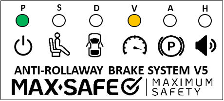
When the ‘P’ and ‘V’ LEDs flash alongside a beep every 30 seconds from the LED module’s buzzer, and the MSB Fault Light remains constantly illuminated when the ignition is turned to ON,

The fault conditions will be one of below:
Conditions for setting fault
- No speed signal is detected.
- The MSB ECU input speed signal device is incorrectly set for vehicle application.
- The vehicle is travelling at over 30km/h, the calculated road speed of the MSB ECU differs from the GPS speed by more than 20%.
- MSB ECU is not receiving the vehicle CAN messaging.
- Internal MSB ECU fault
NOTE: The ‘V’ LED should be ON when the vehicle is stationary, and OFF when the vehicle is travelling at or above 10km/h.
NOTE: (NO vehicle CAN) fault will be displayed if DIP switch 3 in the MSB ECU is in the ON position, and the Vehicle CAN is not connected.
NOTE: In dual control vehicles a seat isolation connector will need to be installed in the observer’s seat to enable dual occupancy. It is recommended that the observer occupies the left-hand seat during vehicle testing.
NOTE: Vehicle speeds MUST be confirmed via a GPS device. GPS reading is most accurate when travelling at a constant speed. The vehicle speedometer will not be accurate enough at speeds 10km/h or lower.
After completing diagnosis and rectifying any faults, a full system test must then be performed and documented on the Systems Confirmation Test – MAX-SAFE Anti-Rollaway Brake System test sheet prior to returning the vehicle to service.
2. Diagnostic Procedure
Ensure that ALL testing is conducted in a controlled, safe, and legal manner. It is recommended that an observer watches the status of the system whilst testing is being conducted.
STEP 1: Clear the fault by isolating the vehicle power supply at the batteries for at least 1 second, then reactivate the power supply to the vehicle. Allowing time for GPS Lock to be achieved.
Drive vehicle above 45km/h checking that the speed signal (Speedometer) in the vehicle is operational. Verify the operation of the ‘V’ light.
‘V’ Light turns off below/higher than 10km/h (+-5%): Continue to STEP 2.
‘V’ Light does not turn off: Continue to STEP 3.
Values within range: Verify repair with Full System Test.
NOTE: Please note that this fault can also indicate a possible fault within the vehicle speed signal circuit, for which specialist repair may be needed from the vehicle OEM.
STEP 2: The calibration of the speed signal, and thus the calculated speed value, does not match the GPS speed value. If the system is set to calculate speed from a CAN signal, the vehicle engine ECU settings will need to be verified/ reprogrammed. If the system calculates speed from a VSS signal, the MSB ECU needs to be reprogrammed/replaced.
Verify repair with Full System Test.
STEP 3: The MSB ECU is not receiving a vehicle speed signal. Inspect the CAN or VSS speed signal connection at the body builder connector. Refer to Table 1.
Using a flat blade screwdriver depress locking tabs on either side of the MSB ECU. Check the MSB ECU PCB DIP switch 3 setting is correct for the speed signal used: Refer to Table 1.1
DO NOT MAKE ANY OTHER ADJUSTMENTS INSIDE MSB ECU.
Within specifications: Continue to STEP 4.
Not within specifications: Repair as required and Verify with Full System Test.
Table 1.
Description | Colour | Pin location (MSB) | Expected Voltages |
CAN HIGH | Yellow | Pin 5 | 2.7V |
CAN LOW | Green | Pin 8 | 2.4V |
(VSS) Vehicle speed signal (PPK) | Brown | Pin 7 | N/A |
Table 1.1
DIP Switch | Speed Input |
ON | Vehicle CAN Input |
OFF | Vehicle speed signal (PPK) |
STEP 4: The ECU has failed. This scenario is unlikely: repeat all testing again to ensure that it is the ECU that has failed. If all testing has been repeated and testing still indicates that the ECU has failed, replace the ECU.
Verify repair with Full System Test.
3. Full System Test
Undertake a full system test of the MAX-SAFE Brake System and document the results on the test sheet found within the document Systems Confirmation Test – MAX-SAFE Anti-Rollaway Brake System prior to returning the vehicle to service.
Should the testing outlined within the Systems Confirmation Test fail for any reason, the system must be thoroughly inspected, diagnosed and repaired, as per the relevant Diagnostic Process document, prior to the vehicle being returned to service.
Was this article helpful?
That’s Great!
Thank you for your feedback
Sorry! We couldn't be helpful
Thank you for your feedback
Feedback sent
We appreciate your effort and will try to fix the article