1. Fault Overview
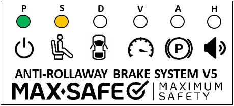
When the ‘P’ and ‘S’ LEDs flash alongside a beep every 30 seconds from the LED module’s buzzer, and the MSB Fault Light remains constantly illuminated when the ignition is turned to ON,

The fault conditions will be one of below:
Conditions for setting fault
- Seat not detected while vehicle travelling over 10km/h for more than 15 seconds.
- Faulty seat sensor.
- Faulty seat sensor extension harness.
- Open/short circuit in seat sensor harness.
- Internal MSB ECU fault.
NOTE: A seat fault will occur after FIVE (5) occurrences of the vehicle park brake being applied with no recognition of the operator being off the seat.
NOTE: A seat fault will occur if the operator is not detected on the seat while vehicle is travelling over 10km/h for over 15 seconds (Do not discount operator error).
NOTE: The MAX-SAFE Anti-Rollaway Brake System™ will continue to function when this fault is active. The Seat sensor is considered to be unoccupied at all times when this fault is active.
The Road speed trigger point is lowered to 5km/h.
NOTE: Only ONE (1) seat can be occupied at any one time.
**Perform a system confirmation test to clear fault**
After completing diagnosis and rectifying any faults, a full system test must then be performed and documented on the Systems Confirmation Test – MAX-SAFE Anti-Rollaway Brake System test sheet prior to returning the vehicle to service.
2. Diagnostic Procedure
Prior to undertaking the following diagnostic procedure, ensure that all electrical connections are securely attached, adjusting as required.
STEP 1: Locate 2-pin connector marked “S-seat” connected to the dual seat adaptor harness and disconnect.
Measure resistance of seat sensors across pins 1 & 2 of connector, confirming resistance changes when sensors are triggered.
Repeat for both seats. Refer to Table 1.
Within specification: Continue to STEP 4.
Not within specification: Continue to STEP 2.
STEP 2: Locate and disconnect 2-pin Molex connector at seat sensor, to isolate extension harness.
Measure resistance of Pin 1 (blue) to blue wire in Molex plug. To verify series resistor, refer to Table 1.
Within Specification: Continue to STEP 3.
Not within specification: Replace extension harness. Verify repair with Full System Test.
STEP 3: Locate 2-pin Molex plug to seat sensor.
Measure resistance across the connector and refer to Table 1.
Within specification: Continue to STEP 4.
Not within specification: Replace seat sensor. Verify repair with Full System Test.
NOTE: Steps 2 & 3 should be repeated for both seats.
Table 1: Expected resistances. All values (+-5%).
Step | Resistance value with extension harness connected. |
Resistance of dual seat adaptor, sensor and extension harness (seats unoccupied). | 101.5 kΩ |
Resistance of dual seat adaptor, sensor and extension harness (1x seat occupied). | 1.5 kΩ |
Resistance of extension harness Pin 1 (blue) to Molex plug (blue). | 1.5 kΩ |
Resistance of Pin 2 (black) to Molex plug (black). | Less than 5Ω |
Resistance of sensor. (seat unoccupied - Measured at rear of seat). | 220 kΩ |
Resistance of seat sensor. (seat occupied - Measured at rear of seat). | Less than 5Ω |
STEP 4: Keep the 2-pin seat sensor “S-Seat” connector disconnected.
Using a multi-meter, perform a voltage test on the wiring harness, while the vehicle power is on.
Test the voltage of the red wire (pin 1) of the 2-pin seat sensor connector when connected to GND (B-). Refer to Table 2.
Test the voltage of the yellow/red wire of the 2-pin seat sensor connector wiring when connected to GND (B-). Refer to Table 2.
Test the voltage of the red wire of the 2-pin seat sensor “S-Seat” connector wiring when connected to the yellow/red wire of the 2-pin seat sensor connector wiring. Refer to Table 2.
Within specifications: continue to STEP 5.
Not within specifications: Replace wiring harness. Verify repair with Full System Test.
Table 2: Voltage of 2-pin seat sensor connector plug wiring (Reference voltage).
Test | 12-volt system | 24-volt system |
Voltage on red wire when connected to GND (B-). | 12V-14V | 24V-28V |
Voltage on yellow/red to GND (B-). | 0V | 0V |
Voltage on red wire when connected to yellow/red wire. | 12V-14V | 24V-28V |
STEP 5 Disconnect the grey connector (12-Way) at the ECU. Locate the yellow/red wire (Pin 12). Perform a continuity test of the yellow/red wire located at the 2-way seat sensor connector (Pin 2). Refer to table 2.1.
Test the resistance of the yellow/red (Pin12) wire from the ECU grey connector when connected to a GND (B-). Refer to Table 2.1.
Within specifications: The ECU has failed. This scenario is unlikely, repeat all testing again to ensure that it is the ECU that has failed. If all testing has been repeated and testing still indicates that the ECU has failed, replace the ECU.
Verify repair with Full System Test.
Not within specifications: The wiring harness has failed; replace the wiring harness, verify repair with Full System Test.
Table 2.1
Test | Resistance |
Resistance yellow/red to yellow/red. | Less than 5Ω |
Resistance yellow/red to GND (B-). | 5.4 kΩ to 5.8 kΩ |
3. Full System Test
Undertake a full system test of the MAX-SAFE Brake System and document the results on the test sheet found within the document Systems Confirmation Test – MAX-SAFE Anti-Rollaway Brake System prior to returning the vehicle to service.
Should the testing outlined within the Systems Confirmation Test fail for any reason, the system must be thoroughly inspected, diagnosed and repaired, as per the relevant Diagnostic Process document, prior to the vehicle being returned to service.
Was this article helpful?
That’s Great!
Thank you for your feedback
Sorry! We couldn't be helpful
Thank you for your feedback
Feedback sent
We appreciate your effort and will try to fix the article