1. Fault Overview
When the MSB Fault Light DOES NOT illuminate while the ignition is turned ON, and:
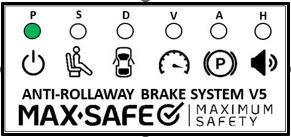
LED Displays only the ‘P’ LED flashing at 2Hz (2 flashes per second), alongside a beep every 30 seconds from the LED module’s buzzer.
OR
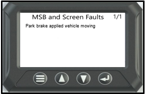
When the LCD screen logs a Reset Switch fault,
The fault conditions will be one of below:
Conditions for setting fault
- Faulty Reset Pressure switch.
- Short circuit in Reset switch harness.
- The system is detecting the vehicle park brake as APPLIED, even though the vehicle is moving at over 10km/h.
Note: The MAX-SAFE Anti-Rollaway Brake System™ WILL NOT operate with this fault active. A vehicle that presents with a Reset Switch fault MUST be repaired prior to the vehicle returning to service.
After completing diagnosis and rectifying any faults, a full system test must then be performed and documented on the Systems Confirmation Test – MAX-SAFE Anti-Rollaway Brake System test sheet prior to returning the vehicle to service.
2. Diagnostic Procedure
STEP 1: Isolate the vehicle’s power supply at the batteries for at least 1 second. Reconnect the power supply to the vehicle. Put the vehicle into the WARNING state by remaining ON the seat, OPENING the door, and DISENGAGING the vehicle’s park brake.
System enters warning state:
Apply vehicle park brake. Visually inspect all connections and Reset pressure switch for damage/corrosion or water ingress.
If no fault is identified. Replace the Reset Switch.
Verify repair with Full System Test.
System does NOT enter the WARNING state: Continue to STEP 2.
STEP 2: Apply the vehicle park brake. Locate and disconnect the reset pressure switch connector and bridge the terminals in the wiring harness (located on the valve assembly).
Repeat STEP 1: Place the vehicle into the WARNING state.
Vehicle goes into the WARNING state,
Replace the Reset Pressure Switch. Verify repair with Full System Test.
System does NOT enter the WARNING state: Continue to STEP 3.
STEP 3: Perform visual inspection of harness for any damage, corrosion or water ingress at the connectors and terminal connections.
Replace connections or Reset pressure switch if conditions present.
With a multi-meter, measure voltage at (R-Reset) connector pin 1 (red wire) to GND (B-). Refer to table 1.
Disconnect grey (12 pin) connector at MSB ECU. Measure voltage on Pin 11 (blue wire) to GND (B-), bridge (R-Reset) connector (pins 1 & 2). Verify at grey (12 pin) connector voltage. Refer to table 1.
Within specification: Replace Reset pressure switch.
Not within specification: Replace wiring harness.
Verify repair with Full System Test.
Table 1: 2-pin reset pressure switch connector plug wiring.
Test | 12-volt system | 24-volt system |
Voltage on red wire when connected to GND (B-). | 12V – 14V | 24V – 28V |
Voltage blue wire pin 11 (no bridge). | 0v | 0v |
Voltage on blue wire pin 11 (bridged). | 12V – 14V | 24V – 28V |
3. Full System Test
Undertake a full system test of the MAX-SAFE Brake System and document the results on the test sheet found within the document Systems Confirmation Test – MAX-SAFE Anti-Rollaway Brake System prior to returning the vehicle to service.
Should the testing outlined within the Systems Confirmation Test fail for any reason, the system must be thoroughly inspected, diagnosed and repaired, as per the relevant Diagnostic Process document, prior to the vehicle being returned to service.
Was this article helpful?
That’s Great!
Thank you for your feedback
Sorry! We couldn't be helpful
Thank you for your feedback
Feedback sent
We appreciate your effort and will try to fix the article